
The Design – CFD Simulation of Combustion Chamber Model with NOx and SOx | ANSYS Fluent
This simulation is about a CFD Simulation of Combustion Chamber Model with NOx and SOx using ANSYS Fluent software. We perform this CFD project and investigate it by CFD analysis.
A combustion model that includes nitrogen oxides (NOx) and sulfur oxides (SOx) must account for the formation of these pollutants in addition to the standard thermodynamic and fluid dynamic calculations of the combustion process. The specific sub-models for NOx and SOx depend on the fuel type, combustion conditions, and desired level of computational detail.
General modeling approach
Modeling NOx and SOx typically involves adding species transport equations to a standard combustion model, which solves for the fuel and oxygen consumption. This can be done as a post-processing step or by fully coupling the pollutant chemistry with the main combustion reactions.
A full computational fluid dynamics (CFD) model for pollutants includes several coupled components:
- Fluid dynamics model: Solves for the turbulent flow field.
- Combustion model: Accounts for the main reactions, heat release, and temperature distribution.
- NOx and SOx sub-models: Calculate the formation and destruction of pollutant species using chemical kinetics.
- Radiative heat transfer model: Essential for high-temperature combustion, especially in industrial boilers.
NOx formation models
Nitrogen oxides are produced primarily through three mechanisms, which must be incorporated into the model.
1. Thermal NOx
Thermal NOx is formed from the reaction of molecular nitrogen ![]() and oxygen
and oxygen ![]() in the combustion air at very high temperatures (typically above 1800 K). This is modeled using the Zeldovich mechanism, which includes three main reactions:
in the combustion air at very high temperatures (typically above 1800 K). This is modeled using the Zeldovich mechanism, which includes three main reactions:
Modeling thermal NOx involves tracking the radical concentrations (O, OH, H), which are often simplified using a quasi-steady-state assumption for less computationally intensive models.
- Fuel nitrogen release: The fuel nitrogen is released during devolatilization to form volatile intermediate species, such as hydrogen cyanide (HCN) and ammonia
 .
. - Intermediate oxidation: HCN and can either be oxidized to NO or reduced back to stable nitrogen
 .
. - Char nitrogen oxidation: The nitrogen remaining in the solid char is oxidized to NO during the heterogeneous combustion of the char.
The relative importance of oxidation versus reduction depends heavily on the local oxygen concentration. Models must account for both homogeneous and heterogeneous reactions.
Prompt NOx is formed in the fuel-rich regions of the flame front when hydrocarbon radicals react with molecular nitrogen. The key reactions involve the formation of hydrogen cyanide (HCN) from atmospheric nitrogen:
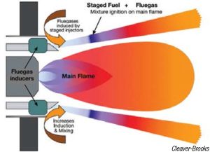
Figure 1. Burners with fuel staging inhibit NOx production
- Sulfur release: For solid fuels like coal, sulfur is released from both the volatile matter and the char during combustion.
- Intermediate formation: The released sulfur rapidly forms intermediate species such as hydrogen sulfide
 or sulfur monoxide (SO).
 - Oxidation to
 : These intermediates quickly oxidize to through reactions with oxygen and radicals:
-
- Oxidation to
 : A smaller portion of is further oxidized to . The rate of this conversion is highly dependent on temperature, the presence of catalysts, and radical concentrations. The reaction can be modeled as:
-
This analysis has tried to simulate and analyze CFD Simulation of Combustion Chamber Model with NOx and SOx using ANSYS Fluent software.
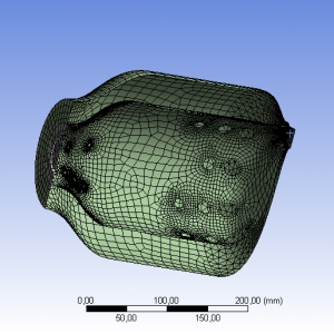
Geometry & Grid
The geometry required for this analysis was generated by Ansys Design Modeler software. The meshing required for this analysis was also generated by Ansys Meshing software. The mesh type used in this analysis is Face Meshing. The total number of surface area (approx.) properties for geometry is 99750 mm².
Model
In this analysis, the NOx and SOx species transport, reaction for models is used to check the fluid flow.
Boundary Condition
The flow of air inlet design modeler geometry for this analysis is considered as a mass flow rate and is 0.118 kg/s. The species mass fractions fuel inlet for o2 is equal to 0.23. The flow of fuel inlet design modeler geometry for this analysis is considered as a mass flow rate and is 0.000172 kg/s. The species mass fractions fuel inlet for ch4 is equal to 1. The flow output range is also considered as a pressure outlet for the flow output region and gauge pressure is equal to 0.
Sizing
According to the type of flow, the coupled algorithm is used to discretize the Pressure-Velocity Coupling of the solution method. The pseudo transient has been used in the transient formulation.
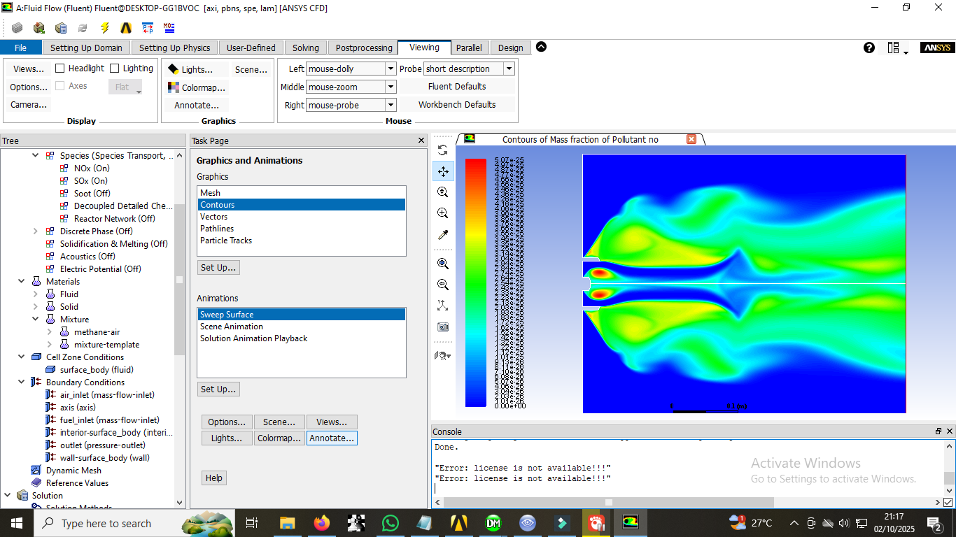
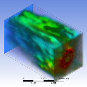
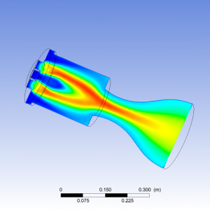
The results are presented as Mass Fraction of Pollutant NO as well as countours.
The Design Services
We also accept all CFD projects using ANSYS Fluent and ANSYS CFX. Our workshop has gathered experts in different engineering fields so as to ensure the quality of CFD simulations. One of our objectives is to boost the use of powerful computational fluid dynamics methods and also teach the engineers and those who seek professional knowledge in CFD.
ِDoing CFD projects will be faster and easier with our services. Call us for training in CFD applications and CFD packages. Our professional CFD engineers offer you professional consultation and technical supports for your academic CFD projects and industrial CFD projects. We offer you CFD learning, CFD project by ANSYS Fluent and ANSYS CFX, CFD consulting by ANSYS Fluent and ANSYS CFX, CFD service by ANSYS Fluent and ANSYS CFX, ANSYS Fluent and ANSYS CFX project, ANSYS Fluent and ANSYS CFX thesis, ANSYS Fluent and ANSYS CFX simulation, ANSYS Fluent and ANSYS CFX paper regeneration, ANSYS Fluent and ANSYS CFX academic project, ANSYS Fluent and ANSYS CFX industrial project, ANSYS Fluent, and ANSYS CFX research project, and low CFD Price. Moreover, we have years of experience in coordinating CFD projects. Therefore, we are ready to perform your CFD simulations in different engineering fields.

Reviews
There are no reviews yet.