
The Design – Analysis Conformal & Non-Conformal Meshing on Sliding Triple Plate | Ansys Fluent
This simulation is about an Analysis Conformal & Non-Conformal Meshing on Sliding Triple Plate using ANSYS Fluent software. We perform this CFD project and investigate it by CFD analysis.
A sliding mesh requires a non-conformal mesh setup, where two distinct mesh zones move independently and are connected via an interface for solution interpolation. A conformal mesh, which has matching nodes at interfaces, is not suitable for a sliding mesh because it would prevent the relative motion between zones. Therefore, the non-conformal mesh is the necessary mesh type for a sliding mesh simulation, despite potential interpolation errors.
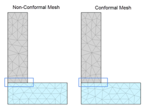
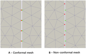
Picture 1. A conformal mesh shows perfect node-to-node alignment across the boundary & A non-conformal mesh allows for great flexibility by connecting two zones with different mesh densities, which requires an interface to manage the date
Conformal vs. Non-Conformal Meshing in Sliding Mesh Simulations
| Feature | Conformal Meshing | Non-Conformal Meshing |
|---|---|---|
| Interface | Nodes and elements align perfectly at the interface. | Nodes do not match across the interface; meshes are not connected. |
| Sliding Mesh Compatibility | Not used for sliding meshes because it prevents relative motion. | Required for sliding meshes because it allows for independent motion of zones. |
| Solution Transfer | No interpolation is needed at the interface. | Solution data is interpolated across the interface to connect zones. |
| Accuracy | Higher accuracy due to no interpolation loss. | Potential for interpolation errors at the interface. |
| Setup Complexity | Can be more challenging to set up for complex geometries. | Easier to generate for complex multi-body systems. |
| Computational Performance | More computationally efficient due to no interpolation. | Less computationally efficient due to the interpolation step. |
- A non-conformal mesh is the correct choice for a sliding mesh simulation because it allows for the relative motion between different parts of the domain.
- The primary downside of a non-conformal approach is the need for interpolation, which can introduce errors and computational overhead.
- A conformal mesh is used when parts of the geometry are stationary or have a shared, unmoving boundary, as it provides greater accuracy and efficiency.
- For a sliding mesh, the non-conformal interface is crucial. For the most accurate results, it’s best to ensure the cell size is small enough, especially near the interface, and the time step is small enough to accurately capture the relative motion.
In this analysis, it has been made to simulate and Analysis Conformal & Non-Conformal Meshing on Sliding Triple Plate using ANSYS Fluent software.
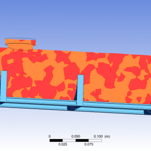
Geometry & Grid
The geometry required for flow analysis in a Sliding Triple Plate is produced by ANSYS Fluent software. The generated grid is also produced by the same software for this geometry, which is entirely of an unstructured type. The total number of volume properties for geometry is 92270 mm³.
Model
For analysis of the mixture process, a k-epsilon (2 eqn) viscous model is used to simulate fluid flow. Standard has been used for the K-Epsilon model. Standard Wall Functions are used for Near-Wall Treatment.
Boundary Condition
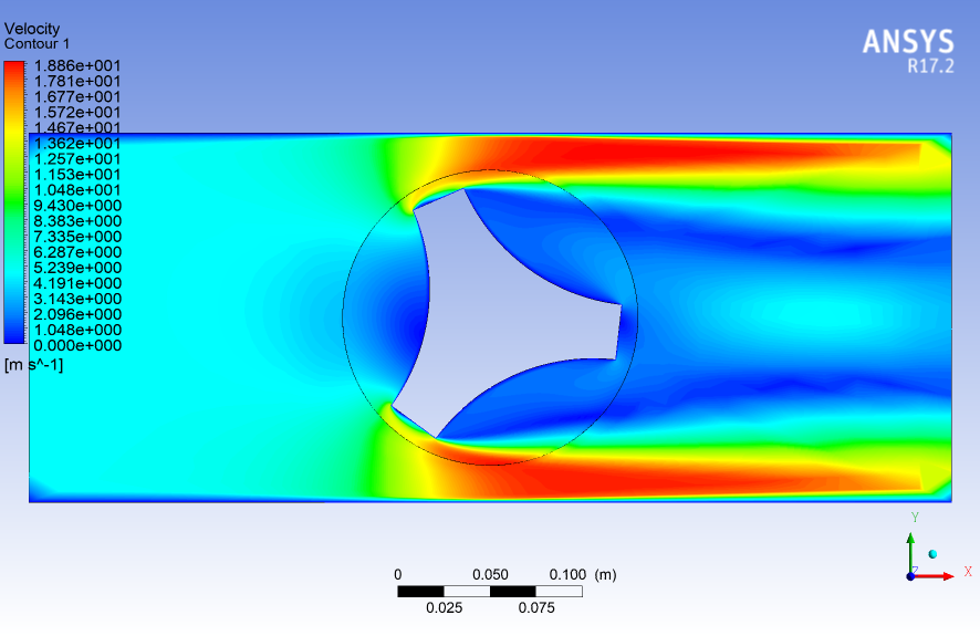
The flow input for this analysis is defined as the VELOCITY INLET for input velocity magnitude is 5 m/s. The walls of the Triple Plate are defined as Moving Wall for Wall Motion. The output flow type is PRESSURE OUTLET, and the gauge pressure is equal to 0.
Discretization of Equations
According to the type of flow, the Coupled algorithm is used to discretize the Pressure-Velocity Coupling of the solution method. The momentum, turbulent kinetic energy, turbulent dissipation rate, and energy have been discretized in the Second Order Upwind.
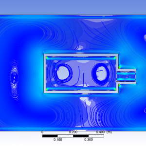
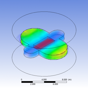
The results are presented as velocity contours and temperature contours as well as volume rendering.
The Design Services
We also accept all CFD projects using ANSYS Fluent and ANSYS CFX. Our workshop has gathered experts in different engineering fields so as to ensure the quality of CFD simulations. One of our objectives is to boost the use of powerful computational fluid dynamics methods and also teach the engineers and those who seek professional knowledge in CFD.
ِDoing CFD projects will be faster and easier with our services. Call us for training in CFD applications and CFD packages. Our professional CFD engineers offer you professional consultation and technical supports for your academic CFD projects and industrial CFD projects. We offer you CFD learning, CFD project by ANSYS Fluent and ANSYS CFX, CFD consulting by ANSYS Fluent and ANSYS CFX, CFD service by ANSYS Fluent and ANSYS CFX, ANSYS Fluent and ANSYS CFX project, ANSYS Fluent and ANSYS CFX thesis, ANSYS Fluent and ANSYS CFX simulation, ANSYS Fluent and ANSYS CFX paper regeneration, ANSYS Fluent and ANSYS CFX academic project, ANSYS Fluent and ANSYS CFX industrial project, ANSYS Fluent, and ANSYS CFX research project, and low CFD Price. Moreover, we have years of experience in coordinating CFD projects. Therefore, we are ready to perform your CFD simulations in different engineering fields.

Reviews
There are no reviews yet.